
Bon ça veux sûrement rien dire pour vous. Mais j’ai configuré un service (normalement pour gérer des batteries externe) sur mon #RaspberryPiZero pour pouvoir changer ses réglages réseaux Wi-Fi via Bluetooth.
Recherches récentes
Options de recherche

#raspberrypizero
0 message0 participant0 message aujourd’hui


MiniDexed EuroRack PCB Build Guide
Here are the build notes for my MiniDexed EuroRack PCB Design.
This is a DIY module only for use in my own DIY system.
Do NOT use this alongside expensive modules in an expensive rack. It is highly likely to cause problems with your power supply and could even damage your other modules.
Warning! I strongly recommend using old or second hand equipment for your experiments. I am not responsible for any damage to expensive instruments!
If you are new to single board computers, see the Getting Started pages.
Bill of Materials
- MiniDexed EuroRack PCB (GitHub link below)
- Front panel
- Raspberry Pi Zero (1 or 2)
- GY-PCM5102 module
- 128×32 SSD1306 OLED display module (pins order: GND-VCC-SCL-SDA)
- 1x L7805 regulator
- 1x H11L1 optoisolator
- 1x 1N5817 Schottky diode
- 1x 1N4148 or 1N914 signal diode
- 1×220Ω, 1×470Ω resistors
- 5x 10nF ceramic capactiors
- 3x 100nF ceramic capacitors
- 2x 47uF electrolytic capacitors (low profile if possible – see text)
- 1x switched rotary encoder with a threaded shroud and nut
- 2x tall tactile buttons – 6x6mm base, at least 12mm height (it needs to poke through the panel!)
- 16-way shrouded EuroRack style power header.
- 40-way GPIO header (optional: extended – see discussion).
- Pin-headers and connecting wires.
Also required: 3.5mm panel mount sockets for audio and MIDI – I use different types, but it will depend on the panel used (see panel discussion).
Build Steps
Taking a typical “low to high” soldering approach, this is the suggested order of assembly:
- Resistors and diode on the top.
- H11L1 (assuming soldered directly to the PCB).
- Disc capacitors on the top.
- Diode and disc capacitor on the bottom.
- Electrolytic capacitors on the bottom.
- GPIO and 16-way power socket on the bottom.
- Buttons and encoder on the top.
- GY-PCM5102 module (see photos for steps required prior to fixing).
- SSD1306 (see photos for steps required prior to fixing).
Here are some build photos and more details of the steps involved.
Note: Most of these photos show the build for V0.1 of the PCB. There are some minor updates in V0.2 which will be noted where relevant.
The power circuit on the underside of the board has two options for mounting the regulator. It can go either vertically or horizontally, but with the tab up. Both methods use the same solder holes. Which is chosen will largely depend on what heatsink options there are.
Note: the first version of the board only had a single option, with the tab down, making contact with the PCB. This didn’t really work from a cooling perspective, hence the change.
The following “in progress” photos still show the first version of the board with the regulator the other way around, an additional resistor, omitted from V2, and the diode in a different place.
Note that low-profile capacitors may be required as they will sit underneath the Raspberry Pi Zero. If the regulator is “standing up” then it should be possible to bend the capacitors over into the space reserved for the regulator.
The GPIO headers have to allow enough space for the Zero to be mounted and not interfere with the PCM5102. See discussion below.
The EuroRack headers need to be correctly oriented and shrouded headers are strongly recommended.
The SSD1306 requires additional spacers on the pins to raise it above the PCB for presentation closer to the front panel.
The PCM5102 must have its solder jumpers configured, if not set already, and requires both sets of pin headers adding.
In the photo below, the PCM5102 has zero-ohm, surface mount resistors as jumpers – but it is really hard to see! On first glance, it looks like there is no link configured at all, but they are connected as: 1L, 2L, 3H, 4L.
These modules have to be added after the other components, as they prevent access to the solder pads during assembly.
GPIO Header Options
One option is to use extended headers, which ought to allow room for the Zero and a heatsink (if required) on the main BCM chip. Note: A V2 Pi Zero could probably benefit from a heatsink I’d imagine if running fully processing all 8 tone generators.
Another option is to remove the on-board 3.5mm, SMT, audio jack on the PCM5102 as shown below, and use “normal” sized GPIO headers.
If non-extended GPIO header is used then, as already mentioned, low-profile electrolytic capacitors may be required as they are positioned underneath the Pi Zero too.
Power Options
As previously mentioned, there wasn’t really much choice when it came to mounting the power regulator for V1 of the board, but in V2 I’ve positioned it differently to allow it to be “tab up” or upright.
The upright positioning was hopefully placed so that a long, thin heatsink could be mounted alongside the Pi. This shows one of those heatsinks you can get for M2 SSD cards. I figure that drilling a hole in it would do the trick, but I’ve not actually done this myself (see below).
The solution I went with in the end was to actually replace the 7805 with a 7805-compatible DC-DC buck converter. These are available fairly cheaply online.
These work a lot more efficiently than a 7805, so especially when drawing 300mA or so from a Pi Zero 2 whilst dropping from 12V down to 5V, they still have no need of a heatsink.
The downside of using these (apparently) is that as a switching power unit, they can be pretty electrically noisy. But as I’m powering a microcontroller rather than a pure analog circuit in the first place, I decided it probably wasn’t going to be making things much worse. This is hardly a high quality, electrically clean build anyway!
Final Assembly
Required Components to use my panel:
- MiniDexed EuroRack Panel (see Github link below).
- Raspberry Pi Zero (1 or 2) with GPIO header pins.
- MiniDexed EuroRack PCB as described above.
- Panel mount 3.5mm TRS socket for MIDI. 6mm diameter hole assumed.
- Panel mount 3.5mm TRS socket for audio. 8mm diameter hole assumed.
- 2.5mm mounting posts, screws and nuts.
I’m using the same designs of TRS sockets for MIDI and audio that I use in all my modules. These need mounting on the panel. Soldering will come in a moment.
I found that with the GPIO header height I was using, alongside the final height of the SSD1306, height of the buttons, and the encoder’s shroud, that the following mountings were required:
- 2x black nylon 2.5mm 6mm screws
- 2x black 10mm 2.5mm spacers
- 2x white 8mm 2.5mm spacers with screws
- 2x white nylon 2.5mm 6mm screws
An alternative build had a slightly larger gap (due to using 12mm buttons) so required four sets of 10×2.5mm spacers.
Another quirk of my first build was that I only had 9mm high buttons which wasn’t quite enough to reach through the panel. Ideally a 11mm or larger button would be required.
But this allowed me to 3D print a white 2.8mm diameter, 3.0mm high, extension that I could glue on the top, meaning that the exposed part of the button was white, matching the panel.
My second build used a black panel and 12mm buttons, but as already mentioned this meant the panel had to use 10mm spacers instead of 8mm spacers. One issue with that is that there isn’t much of the encoder shaft exposed. I found some knobs that worked ok, but my preferred (cheap) knobs could not be fitted and still allow the encoder switch to function.
In summary, there is still a fair bit of trial and error with each build depending on the exact combinations of screen height, encoder shaft length, button length and so on.
Once the PCB and panel is fixed together then the two 3.5mm sockets can be soldered to the PCB (or connected using headers if that was the preferred option).
Recall that MIDI IN does not required a GND connection. Also double check which solder tabs correspond to the TIP and which to the RING, which should match the “T” and “R” labels on the PCB (“S” is for shield, i.e. GND).
Testing
I recommend performing the general tests described here: PCBs.
Then, prior to plugging in the RPi Zero, do the following:
- Verify that the 12V and GND connections of the EuroRack connector have no shorts.
- Power up the board (no Pi) and verify that there is a 5V signal present and going to the PCM5102 and SSD1306. The PCM5102 should have its red power LED on.
Only then power off, plug in the RPi Zero with an SD card containing MiniDexed (configuration below) and verify that the display, encoder, buttons, MIDI IN, and audio out are all working.
MiniDexed Configuration
The following are the key MiniDexed.ini configuration options required:
SoundDevice=i2s

SSD1306LCDI2CAddress=0x3C
SSD1306LCDWidth=128
SSD1306LCDHeight=32
LCDColumns=20
LCDRows=2

ButtonPinBack=5
ButtonActionBack=click
ButtonPinSelect=11
ButtonActionSelect=click
ButtonPinHome=6
ButtonActionHome=click
ButtonPinShortcut=11

EncoderEnabled=1
EncoderPinClock=10
EncoderPinData=9
PCB Errata
As already noted, there were a number of issues with the first version of the PCB, but these should have been addressed in the published version.
As the time of writing, there are no further known issues with V0.2 of the PCB.
Enhancements:
- I feel like the power situation ought to be better. One option could be to break out a USB connection to the Zero directly allowing the use of a standard “wall wart” type supply.
- Another option might be to make use of the solder pads on the rear of a Zero (like the Zero STEM does).
- It might also be useful to provide a configurable (e.g. solder bridge) link to enable the EuroRack +5V supply as an option.
- There are already options to use internal (within a rack) links for MIDI and audio if required using the pin headers on the PCB, but it might be nice to allow a choice between panel or rear connectors.
Closing Thoughts
I’m still not fully happy with the longer-term implications of how I’m powering these boards, but I’ll see how things go. Those DC-DC converters seem like a feasible option so I’ll see how they perform.
The panel height issue could be better too – it would be nice to have a recommended set of components and a known useful size of spacers, but there is still a fair bit of trial an error at the moment with each build.
Also, sometimes the display height isn’t perfect, as shown below. I might 3D print a display bezel or surround to help.
The end results looks pretty good though, so for this stage in my thinking about these, I’m pretty pleased with how this has ended up.
But one last time, just to make my position totally clear: this is a DIY system and should only be used with other DIY modules you wouldn’t mind too much losing.
It is NOT for use alongside other commercial (expensive) or treasured modules. There are commercial versions of MiniDexed apparently for that, that I have no experience of.
Kevin


DIY Pipe Inspector Goes Where No Bot Has Gone Before - If you think your job sucks, be grateful you’re not this homebrew sewer inspection... - https://hackaday.com/2024/11/27/diy-pipe-inspector-goes-where-no-bot-has-gone-before/ #remotelyoperatedvehicle #raspberrypizero #robotshacks #inspection #ethernet #sewer #pip #poe #rov
Hackaday · DIY Pipe Inspector Goes Where No Bot Has Gone BeforeIf you think your job sucks, be grateful you’re not this homebrew sewer inspection robot. Before anyone gets upset, yes we know what [Stargate System] built here isn’t a robot at all; i…
Pi Zero Power Optimization Leaves No Stone Unturned - If you’ve ever designed a battery-powered device with a Pi Zero, you have no doubt... - https://hackaday.com/2024/10/03/pi-zero-power-optimization-leaves-no-stone-unturned/ #powerconsumption #raspberrypizerow #raspberrypizero #raspberrypi #solarhacks #profiling #profiler #pizero2 #pizerow #how-to #pizero #zerow
Hackaday · Pi Zero Power Optimization Leaves No Stone UnturnedIf you’ve ever designed a battery-powered device with a Pi Zero, you have no doubt looked into decreasing its power consumption. Generic advice, like disabling the HDMI interface and the onbo…


Remember the #Sega #Dreamcast #vmu?
It'd be cool to build a case for a M.2 #NVMe with an integrated screen and gamepad buttons like these, maybe run a little #raspberryPiZero in it?

Retro Inspired Cyberdeck Scrolls Around Cyberspace - It’s difficult to nail down exactly what counts as a “real” cyberdeck in this brav... - https://hackaday.com/2024/07/25/retro-inspired-cyberdeck-scrolls-around-cyberspace/ #peripheralshacks #raspberrypizero #rotaryencoder #scrollwheel #cyberdecks #cyberdeck
Hackaday · Retro Inspired Cyberdeck Scrolls Around CyberspaceIt’s difficult to nail down exactly what counts as a “real” cyberdeck in this brave new era of bespoke computing. But at the minimum, most in the community would agree that a prop…


 | R.I.P Natenom
 I should open the window. My #DIY #CO₂ meter went full tilt.
(Source code and instructions at https://github.com/xtaran/co2-led-meter)

PhotonPower Zero For Effortless Solar Pi Zero Projects - A Pi Zero doesn’t need much to sustain itself, and it’s projects like the PhotonPo... - https://hackaday.com/2024/04/02/photonpower-zero-for-effortless-solar-pi-zero-projects/ #raspberrypizero #raspberrypi #solarhacks #solarpanel #solarpower #solar
Hackaday · PhotonPower Zero For Effortless Solar Pi Zero ProjectsA Pi Zero doesn’t need much to sustain itself, and it’s projects like the PhotonPower Zero that remind us of it its low appetite when we need this reminder most. The PhotonPower Zero bo…
AI-Powered Bumper Sticker Provides Context-Sensitive Urban Camouflage - While we absolutely support the right of everyone to express their opinions, it se... - https://hackaday.com/2024/02/14/ai-powered-bumper-sticker-provides-context-sensitive-urban-camouflage/ #transportationhacks #raspberrypizero #bumpahstickah #bumpersticker #geolocation #politics #opinion #geopy #hdmi #gps
Hackaday · AI-Powered Bumper Sticker Provides Context-Sensitive Urban CamouflageWhile we absolutely support the right of everyone to express their opinions, it seems to us that it’s rarely wise to turn your vehicle into a mobile billboard for your positions. Aside from p…
Raspberry Pi Zero Powers Custom Camera Platform - These days, most of us are carrying a fairly impressive digital camera with us at ... - https://hackaday.com/2023/12/19/raspberry-pi-zero-powers-custom-camera-platform/ #digitalcamerashacks #raspberrypizero #raspberrypi #pihqcamera #diycamera
Hackaday · Raspberry Pi Zero Powers Custom Camera PlatformThese days, most of us are carrying a fairly impressive digital camera with us at all times. But as capable as the hardware and software of a modern smartphone may be, there’s still plenty of…
This is a MIDI interface for a Raspberry Pi Zero. It is designed to be stackable so it can be used with my RPi Zero MiniDexed IO Board PCB.
- Here is the Raspberry Pi Zero MIDI PCB Build Guide.
Warning! I strongly recommend using old or second hand equipment for your experiments. I am not responsible for any damage to expensive instruments!
If you are new to microcontrollers and single board computers, see the Getting Started pages.
The Circuit
This is the fully buffered MIDI IN/OUT/THRU circuit I’ve used several times before, loosely based on the design used in the Clumsy MIDI board. This provides IN and OUT linked to the RPi’s RX/TX pins whilst also including a hardware MIDI THRU hanging straight off the RX pin too.
It is 3V3 compatible for use with the Raspberry Pi but the 74HCT14 acts as both a buffer and level shifter so that the MIDI OUT and THRU portions of the circuit present a 5V MIDI design to the outside world. This means that the HCT variant of the 74HCT14 is required, not the HC version. It also means that the H11L1 is powered from 3V3 and the 74HCT14 from 5V.
The schematic itself allows for the use of either TRS (Type A) or DIN MIDI sockets.
This only uses the following RPi GPIO pins:
- GPIO14 (TX)
- GPIO15 (RX)
- 5V
- 3V3
- GND
PCB Design
I’ve just managed to get everything into the footprint of a Pi Zero board as long as I only use MIDI TRS sockets.
I did consider the idea of detachable MIDI DIN sockets too (the schematic includes both) but in the end opted for simplicity and went just with TRS. That option is reserved for a future edition should I wish.
It can’t be seen in the PCB view above, but there is actually a missing link that I’ve missed off when routing the board (the perils of have silkscreen overlaps and elements in your schematic unused in the PCB is not probably paying attention to the DRC…). The 74HCT14 should have pins 2 and 3 tied together, but no link was included. A simple solder bridge should suffice.
Closing Thoughts
I’m annoyed about that missing link, but thankfully it is a pretty easy fix.
Apart from that, I’m pleased with how this has come out. As I say a future edition might include detachable MIDI DIN socket connections too.
Kevin
https://diyelectromusic.wordpress.com/2023/12/12/raspberry-pi-zero-midi-pcb/


Here are the build notes for my RPi Zero MiniDexed IO Board PCB.
Warning! I strongly recommend using old or second hand equipment for your experiments. I am not responsible for any damage to expensive instruments!
If you are new to microcontrollers and single board computers, see the Getting Started pages.
Bill of Materials
- RPi Zero MiniDexed IO Board PCB (GitHub link below)
- SSD1306 OLED 128×32 I2C display (pinout: GND-VCC-SCL-SDA).
- Optional: GY-PCM5102 I2S DAC module.
- 2x 100nF ceramic capacitor.
- 5x 10nF ceramic capacitor.
- 1x Switched rotary encoder (PCB mount, see photos for footprint).
- 2x miniature toggle switches (PCB mount, see photos for footprint).
- 1x 4-way header socket.
- 1x 2×20 GPIO header socket.
Build Steps
Taking a typical “low to high” soldering approach, this is the suggested order of assembly:
- Disc capacitors.
- Button switches.
- GY-PCM5102 module (if used).
- 4-way header for display.
- GPIO header.
- Rotary encoder.
Build Options:
- With DAC: As described below with a GY-PCM5102 module on the board. The display will have to be fitted in a 4-way header socket and raised above he PCM5102 once fitted.
- No DAC: It is possible to use a PWM audio add-on for the Zero and not bother with a DAC. More details here: Raspberry Pi Zero PWM Audio Interface.
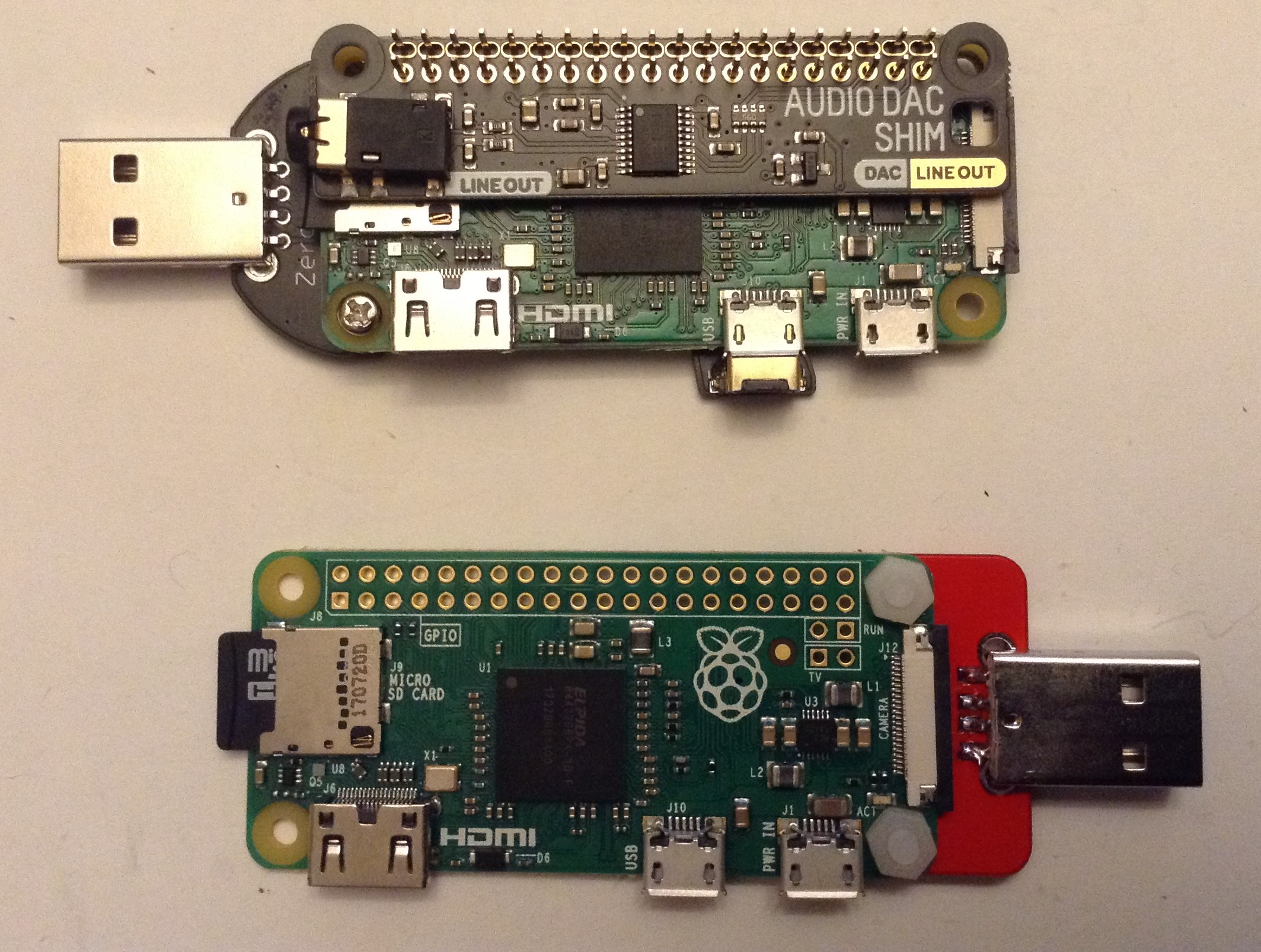
- External I2S DAC: It is possible to use something like the Pimoroni Audio DAC SHIM between the Zero and the MiniDexed IO board. More details here: A DX7 USB Dongle.
Note: in the case where the SSD1306 is soldered directly to the board, e.g. if no PCM5102 is used, the 100nF ceramic capacitor for its supply pins will have to be bent over flat prior to mounting the display.
Here are some build photos.
Prior to soldering on the GY-PCM5102 module, the jumpers on the rear of the board may need to be configured.
Only the 6-way connector is used for connection to the board, but it is recommended that at least a single additional header pin is used on the 9-way header to help physical stability of the final build.
This can be used with any Raspberry Pi, but my main aim was for something that could be used with a Pi Zero acting in USB Gadget Mode for example, with my DX7 USB Dongle as shown below.
Testing
I recommend performing the general tests described here: PCBs.
Once assembled, the correct MiniDexed configuration is required, as described below.
PCB Errata
There are the following issues with this PCB:
- The 5 debouncing capacitors for the encoder and switches are listed on the board as “10p” but they should be “10n” – i.e. 10nF ceramic capacitors.
Enhancements:
- Additional GPIO headers could be added for further expansions – e.g. more buttons.
MiniDexed Configuration
The key elements of the minidexed.ini configuration required to support this board are as follows.
# If in USB Gadget mode - see A DX7 USB Dongle.
USBGadget=1

# Either pwm or i2s
SoundDevice=i2s

LCDEnabled=1
SSD1306LCDI2CAddress=0x3C
SSD1306LCDWidth=128
SSD1306LCDHeight=32
SSD1306LCDRotate=1
SSD1306LCDMirror=0
LCDColumns=20
LCDRows=2

ButtonPinPrev=0
ButtonActionPrev=
ButtonPinNext=0
ButtonActionNext=
ButtonPinBack=5
ButtonActionBack=click
ButtonPinSelect=11
ButtonActionSelect=click
ButtonPinHome=6
ButtonActionHome=click
ButtonPinShortcut=11

EncoderEnabled=1
EncoderPinClock=10
EncoderPinData=9
Closing Thoughts
Whilst it is somewhat irritating to have made the 10p/10n mistake yet again, I’m quite pleased with how these boards have come out.
I have a stackable TRS MIDI interface in the works too which should be able to work with this IO board too.
Kevin
https://diyelectromusic.wordpress.com/2023/12/02/rpi-zero-minidexed-io-board-pcb-build-guide/


The amazing Rene Stange added USB Gadget (i.e. device) support to the Circle bare metal Raspberry Pi environment a while ago so I’ve now incorporated that into MiniDexed. This allows MiniDexed to be used as a USB device – i.e. it can just be plugged into a PC and used via USB MIDI directly, as long as your Raspberry Pi supports USB Gadget mode and you have some means of audio output.
This post looks at how to make a “USB dongle” that is basically a USB MIDI accessible DX7.
A quite note before I start however. Why would someone want to do this? There are several VST DX instruments for PCs if you want DX sounds in your DAW and Dexed itself gives you full access to a DX7 via a software interface.
So there is probably very little practical reason to do this. But personally, I just couldn’t resist the idea of having a plug-in DX7 on a USB stick!
Warning! I strongly recommend using old or second hand equipment for your experiments. I am not responsible for any damage to expensive instruments!
These are the key tutorials for the main concepts used in this project:
If you are new to microcontrollers and single board computers, see the Getting Started pages.
Parts list
- Raspberry Pi Zero, Zero W or Zero W2.
- I2S or alternative audio output for a Pi Zero.
- USB “STEM”, “Zero Dongle” or other USB device connection (micro USB to USB A).
Note: the Pi Zero and Zero W will give access to a single MiniDexed tone generator. The Pi Zero W2, will support 8 tone generators.
Warning: When using a Raspberry Pi in USB Gadget mode, do not plug in its usual power supply! It should be USB “bus powered” only.
The Hardware
Whilst any Raspberry Pi that supports USB Gadget mode could be used with a suitable lead to power and link to MiniDexed, to make a USB “dongle” requires the use of a Pi Zero (any flavour) and a “dongle style” add on.
I’ve used the following:
It will also need a means of outputting audio from the Zero as MiniDexed only supports USB MIDI, not USB audio.
There are several options for audio out on a Pi Zero. By far the easiest is some kind of off-the-shelf I2S audio interface.
A really good, low-profile one ideal for use as a dongle is the Pimoroni Audio SHIM, which can be found here. It doesn’t even need soldering, it can push-fit over the Pi’s GPIO headers, but any I2S audio interface for the Pi can be used as long it doesn’t interfere with the USB plug for the “dongle”.
My ideal combination is the USB STEM and the Pimoroni Audio SHIM as it is both low-profile and has the USB plug at one end and the audio output at the other.
MiniDexed Configuration
Hopefully by the time you read this, USB Gadget support in MiniDexed will be merged into the main code (it is PR567). Details of how to configure it can be found on the wiki here, but the key MiniDexed configuration (minidexed.ini) required for this configuration is as follows:
USBGadget=1SoundDevice=i2s
The rest of the configuration is largely ignored, but things like the LCD, buttons and encoder can simply be disabled (set to 0) as they are not required.
A Single DX7
As mentioned previously if using a Zero V1/W then a single tone generator is available. The MIDI channel it uses will be as defined in the default performance.ini file. It is set to OMNI by default. To change it, change:
MIDIChannel1=<MIDI channel 1 to 16>
The default MIDI configuration for MiniDexed assumes voice changes will be made with a combination of bank select Control Change and Program Change messages with each bank containing 32 voices. But the following configuration allows four banks to be spread across all 128 Program Change values:
ExpandPCAcrossBanks=1
When plugged into a PC it will come up as “MIDI Gadget” as a USB MIDI compatible device. Here it can be seen in MidiOx, being selected as the MIDI output.
I have a MidiOx instrument file with all the voices for Roms 1a/1b/2a/2b/3a/3b/4a/4b selectable via Bank Select messages, and Roms 1a+1b+2a+2b configured for use as a single 128-voice bank via Program Change messages.
Find it on GitHub here. This needs to be copied to the “instr” directory of the MidiOx installation.
In MidiOx, View -> Instrument Panel, select “INS File: DX7ROMS.INS” and then choose one of the following for “instr”:
- “YAMAHA DX7 ROMS” for the individually selectable 8 ROMs.
- “YAMAHA DX7 VOICES” for the first four ROMs to be linked as a 128-voice single bank.
Both views (and voice selections) are shown below.
An 8-DX7 Instrument
If using a Zero 2W then 8 tone generators are available. In that case there is a choice. It can be treated as eight independent tone generators, in which case the MIDI channels for each TG should be set independently.
The following configures TGs 1-8 for MIDI channels 1-8.
MIDIChannel1=1MIDIChannel2=2MIDIChannel3=3...MIDIChannel8=8
At this point, the MIDI interface is the same as before, but changing the MIDI channel will change the tone generator being used.
Alternatively, it is possible to now treat the 8-way TG MiniDexed as a single instrument with much more complex sounds.
If the following setting is enabled in minidexed.ini:
PerformanceSelectChannel=1
This will interpret Program Change messages on MIDI channel 1 as selecting “performances”. Each “performance” is a configuration of up to 8 tone generators with a range of voices and effets.
The full list of default “performances” can be sound by browsing the MiniDexed github repository here.
Once again I’ve added a mode in my MIDIOx instrument file to support performances:
Warning: There is a proviso with this configuration.
At present, MiniDexed loads performances into consecutive “slots” meaning that the numbers in the MiniDexed repository do not relate to the “patch numbers” used over MIDI. The MIDIOx file supports the files in the repository at the time of writing. If new performances are added in some of the gaps (and there are gaps) in the numbering, then the names will be out of sync with what is installed.
Personally I think we need to change this and make the numbers relate to the MIDI program numbers. Watch this space!
Closing Thoughts
As mentioned in the introduction, with a good selection of software synths available that provide a DX7 on a computer for use with a DAW, there is limited use for a “DX7 on a USB stick”.
But I still think this is a pretty neat thing to be able to do, if nothing else, just for the fun of knowing that a $2000 synth from the 1980s can now be replicated with ~$20 worth of hardware that can be plugged into any PC and just “played”.
Kevin
https://diyelectromusic.wordpress.com/2023/11/22/a-dx7-usb-dongle/


Extremely Mini Raspberry Pi Cyberdeck – #raspberrypi #cyberdeck
Introduction
Hi everyone. I recently took part in an episode of The Pi Cast from Tom's Hardware during which I presented my latest project: a Mini (or Tiny!) Raspberry Pi Cyberdeck. You can see the full episode below. Of particular interest is, around the 56s mark, I show how small this really is - Banana fo
Raspberry Pi Pod and micro:bit baseExtremely Mini Raspberry Pi Cyberdeck - #raspberrypi #cyberdeck - Raspberry Pi Pod and micro:bit baseIntroduction Hi everyone. I recently took part in an episode of The Pi Cast from Tom’s Hardware during which I presented my latest project: a Mini (or Tiny!) Raspberry Pi Cyberdeck. You can see the full episode below. Of particular…Read more →
Blackberry Pi Puts Desktop Linux in Your Pocket - Let’s face it — Android wasn’t what most of us had in mind when we imagined having... - https://hackaday.com/2023/08/12/blackberry-pi-puts-desktop-linux-in-your-pocket/ #handheldcomputer #raspberrypizero #handheldshacks #raspberrypi #blackberry #linux
HackadayBlackberry Pi Puts Desktop Linux In Your PocketLet’s face it — Android wasn’t what most of us had in mind when we imagined having Linux running on our phones. While there’s a (relatively) familiar kernel hiding at the co…

Hmm. What should I do with a stealth #linux system? #cyberdeck #3dprinter #wardriving #fpv #drone #warflying #hydroponics #homeautomation #retrogaming
#raspberrypi #RaspberryPiZero #rpi
@rpilocator @adafruit


Encore un #raspberrypizero qui n'aura pas aimé son séjour à l'extérieur.

A répondu dans un fil de discussion
@arturo182: A rather simple project, but I love the outcome: A #RaspberryPiZero based, continuous #CO₂ "Traffic Light" as an indicator when the windows need to be opened for some fresh air, especially more #oxygen: https://github.com/xtaran/co2-led-meter
It requires no soldering, just plug a bunch of components together (should all be available at https://shop.pimoroni.com/) and run a short #Python script.
Motivation was Sensirion's USB CO₂ traffic light where the IMHO rather high thresholds can't be changed.

Old Robotic Vacuum Gets a New RC Lease on Life - To our way of thinking, the whole purpose behind robotic vacuum cleaners is their ... - https://hackaday.com/2022/12/22/old-robotic-vacuum-gets-a-new-rc-lease-on-life/ #reverseengineering #raspberrypizero #magicsmoke #bluetooth #brushless #hoover #roomba #vacuum #esc #rc
HackadayOld Robotic Vacuum Gets A New RC Lease On LifeTo our way of thinking, the whole purpose behind robotic vacuum cleaners is their autonomy. They’re not particularly good at vacuuming, but they are persistent about it, and eventually get th…